After I had the idea, I was deeply challenged by the complexity of the problem, and my hobby during university time became trying to find a method to solve it.
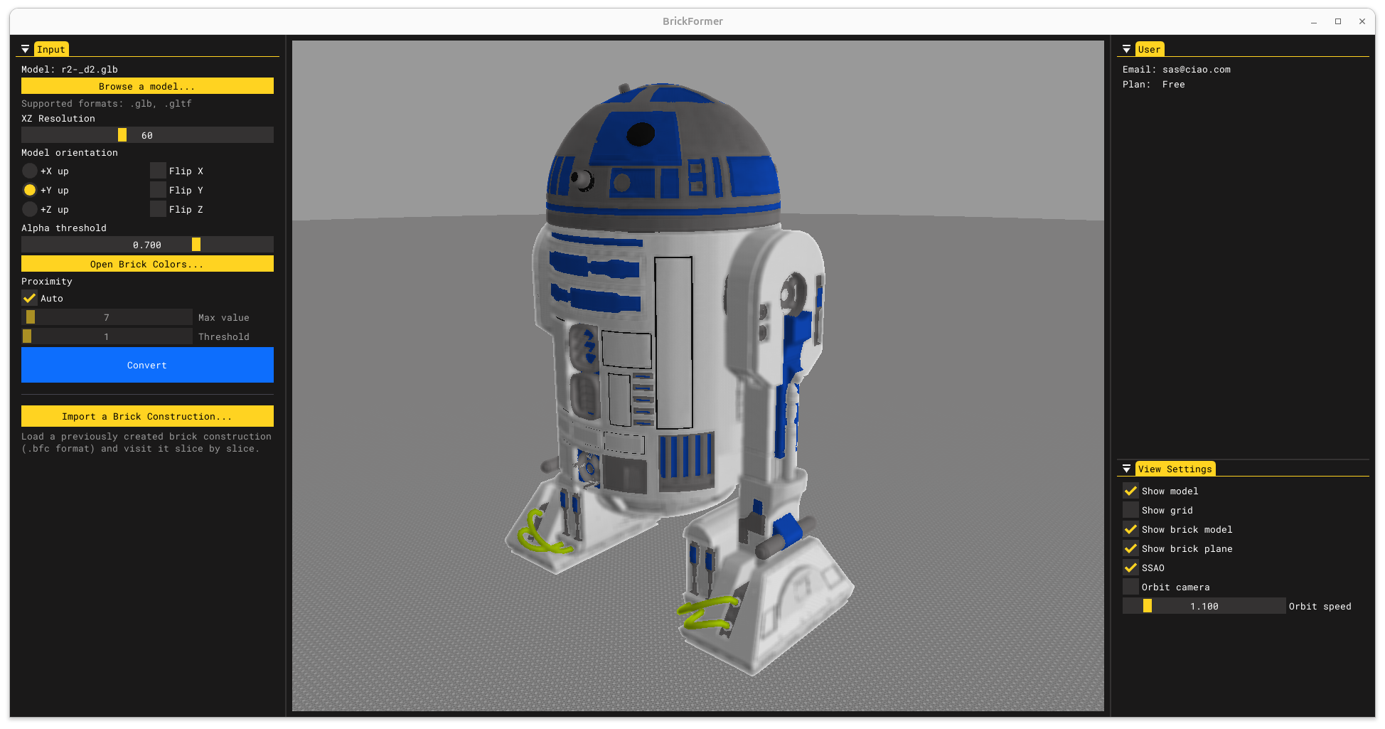
User pipeline
Upload the model
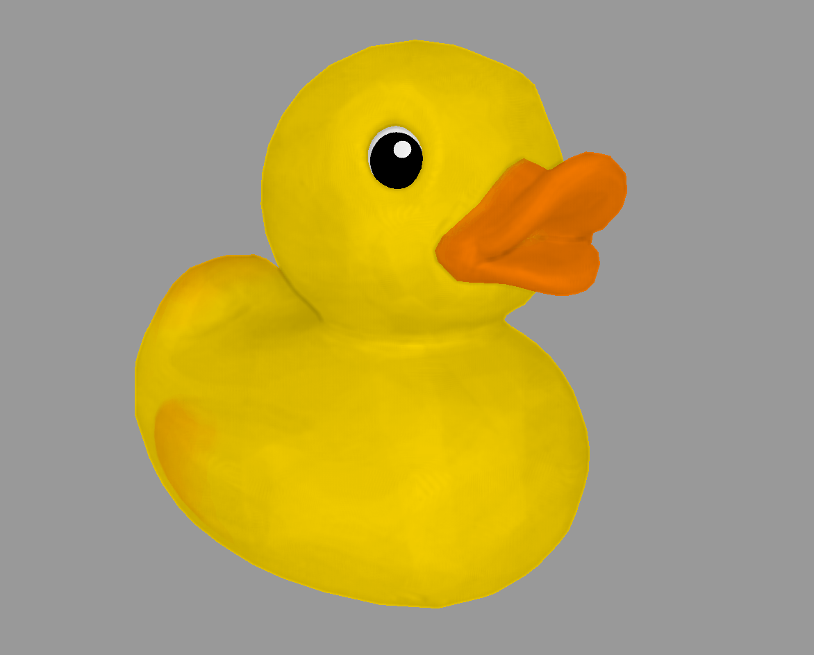
The user uploads a 3D model (picked for example from Sketchfab).
The supported formats are .gltf and .glb.
These are general purpose formats to which any other can typically convert to.
User pipeline
Choose the model orientation
The model orientation can be any.
This depends on which tool was used to craft the model.
Hence why I've provided a functionality to define the up axis and to flip axes.
User pipeline
Choose the grid resolution
The grid resolution defines how many bricks are used in the XZ dimensions (+Y up). The height (i.e. the number of slices) will be proportional to the model size.
User pipeline
Choose the colors to use
I support all common LEGO brick colors available on the market. Via UI, it is possible to exclude colors that must not be used during the conversion, hence defining a custom palette.
User pipeline
Exporting the conversion
- Export the bricks required for the conversion to .lxf, and upload them to BrickLink to purchase them.
- TODO You can export the construction to a full-featured LEGO editor, like BrickLink Studio.
- TODO Export PDF instructions.
- Export the 3D Model of the LEGO construction.
Problem statement
The similarity is defined in terms of shape and color. The "LEGO construction" has a given resolution and is a combination of bricks drawn from a provided discrete set. Among the possible combinations some of them are invalid.
Problem statement
The similarity function
Problem statement
The solution space
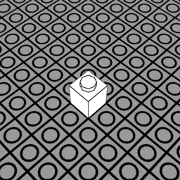
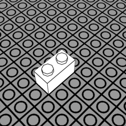
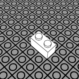
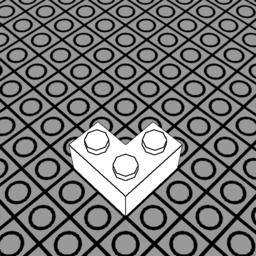
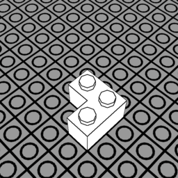
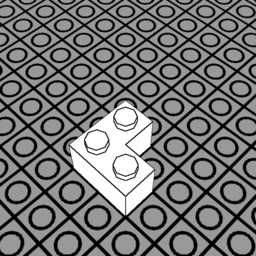
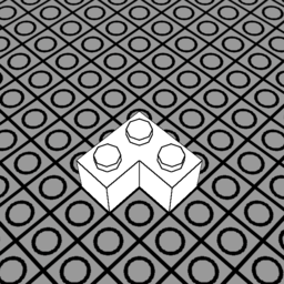
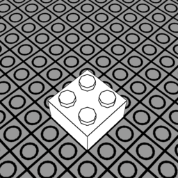
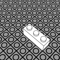
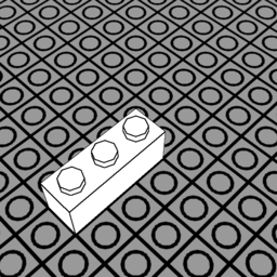
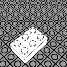
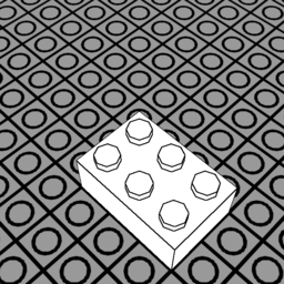
To simplify the problem, the set of available bricks $\mathbb{B}$ is made of standard LEGO bricks (as shown in Figure 1). Different rotations of these bricks are treated as different bricks. Placements locations are binned in voxels within a 3D grid defined by the input resolution $\mathcal{R}$.
Despite these simplifications, the solution space $\mathbb{P}$ remains insanely large:
For every voxel, any combination of bricks could be placed, and of any color.
The cardinality would be:
Where $\mathbb{C}$ is the set of available colors.
The greedy algorithm
Bottom-up, slice-by-slice construction
The model is first sliced into $\mathcal{R}_y$ slices, and each slice is processed incrementally. In this way we can strip the height dimension from the search space:
However, we still didn't get rid of invalid solutions: some solutions could have overlapping bricks, floating bricks or bricks spanning out of the conversion grid. While checking if a brick is floating or out of bounds is simpler in the 2D case (and could be done when evaluating the similarity function), checking if bricks of the same solution are overlapping is not trivial as it requires a second pass and additional storage.
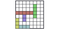
Slicing the model
A kernel is dispatched with one invocation for every triangle. The world-space triangle is intersected against a box representing a voxel of the current slice. If the intersection test succeeds, the voxel is filled with the interpolated triangle's color.


The greedy algorithm
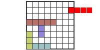
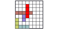
Placement-by-placement construction
This inspired me for the final algorithm: starting from a state $\mathcal{S}_i$ of the construction, all possible placements $\pi$ within the slice are evaluated. Among these, it is picked the placement $\pi^*$ which evaluates the highest to a hand-crafted placement score function $f_{\mathcal{S}_i}$. \[\begin{aligned} \pi^* = \arg\max_{\pi \in \hat{\mathbb{P}}} f_{\mathcal{S}_i}(\pi) \end{aligned} \] Once the placement is selected, it is added to the construction: \[\begin{aligned} \mathcal{S}_{i+1} \leftarrow \mathcal{S}_i \cup \pi^* \end{aligned} \] The process is repeated within the current slice, until the best score remains above a pre-defined threshold $\tau_f$. When this condition is false, it restarts for the next slice until the full height of the construction ($\mathcal{R}_y$) is reached.
The greedy algorithm
Placement score function
After several experiments with different measures, I ended up with: \[\begin{aligned} h_n = 1 - \dfrac{h}{3 \cdot 255} \end{aligned} \] \[\begin{aligned} f_{\mathcal{S}_i}(\pi) = \dfrac{b}{B} \cdot \left( \dfrac{d}{b} + \operatorname{sigmoid}( 32 \cdot (h_n - 0.130) ) \right) + (0.8 \cdot \dfrac{c}{b} + 0.2) \end{aligned} \] Where:
- $b$ is the size of the brick.
- $B$ is the maximum brick size.
- $d$ is the number of different placements on the previous slice that this placement connects.
- $h$ is the Manhattan RGB distance between the brick and the model.
- $c$ is the number of voxels filled by the model's slice, that this placement covers.
As it can be deduced from the above, each variable encodes a local similarity and stability:
- $b$: the larger the brick, the better. This improves stability.
- $d$: the more diverse placements are connected on the previous slice, the more stable it is. For example, avoids making same brick piles.
- $h$: addresses color similarity.
- $c$: addresses structural similarity.
Placement Solver implementation
I've used the global warp ID instead of the global invocation ID, the reason is the latter would neglect warp intrinsics that are useful when having to iterate all cells covered by a single placement.
The global warp ID is expanded into a 3-dimensional coordinate: the XZ of the placement and the brick ID (the type of brick).
__global__ float eval_score(size_t num_possible_placements, ...)
{
    int warp_id = blockIdx.x * 32 + threadIdx.x / 32; // Global warp ID = Placement ID
    if (warp_id >= num_possible_placements) return;

    Placement placement{};
    placement.bid = warp_id % NUM_BRICKS; // Brick ID
    placement.x = (warp_id / NUM_BRICKS) % RESOLUTION_X;
    placement.z = warp_id / (RESOLUTION_X * NUM_BRICKS);

    // ...
Placement Solver implementation
__device__ bool is_outside_or_overlapping(placement, current_placements)
{
    __shared__ int result[32];

    int warp_idx = threadIdx.x >> 5;
    if (IS_FIRST_WARP) result[warp_idx] = false;
    __syncwarp();

    const auto& brick = bricks[placement.bid]; // float[16][16]
    // Iterate the cells covered by the brick in parallel
    iterate_brick_grid([&](int bx, int by) {
        if (brick[by][bx]) {
            int mx = placement.x + bx;
            int my = placement.z + by;

            bool out_of_bounds = mx < 0 || mx >= RESOLUTION_X || my < 0 || my >= RESOLUTION_Y;
            bool overlapping = current_placements.read_pixel(mx, my).x != NO_PLACEMENT_VALUE;
            if (out_of_bounds || overlapping) atomicOr_block(&result[warp_idx], true);
        }
    });
    __syncwarp();

    return result[warp_idx];
}
    // ... eval_reward

    if (is_outside_or_overlapping(placement)) return;

    // ...
Placement Solver implementation
placement are evaluated and aggregated into a final score.Other heuristics are taken:
- "hole filling" placements are prioritized to avoid, for example, gaps in a flat surface
- Degeneration of the shape is avoided by not selecting placements that don't intersect the model enough
    float b = eval_brick_size(placement.brick_id);
    float c = eval_colormap_coverage(placement, voxelized_model_slice);
    float d = eval_connected_bricks(placement, prev_slice);
    float h = eval_colormap_rgb_distance(placement, voxelized_model_slice);

    float bn = float(b) / float(BRICK_MAX_EXTENT_X * BRICK_MAX_EXTENT_Z);
    float cn = float(c) / float(b);
    float dn = float(d) / float(b);
    float hn = std::max(h, 0);
    hn = sigmoid(16.0f * 2.0f * (hn - 0.13071895f)) / (3.0f * 255.0f); // Empirical
    hn = 1.0f - hn;

    // If the placement doesn't intersect any model's voxel,
    // it is only allowed to fill holes!
    if (c == 0) {
        return is_filling_hole(placement) ? bn : -INFINITY;
    }

    // If the placement doesn't cover enough model's voxels, it is discarded
    if (cn < 0.2f) return -INFINITY;

    // Final score
    return bn * (dn + hn) + (0.8f * cn + 0.2f);
LEGO Renderer
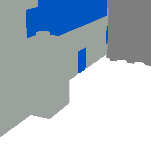
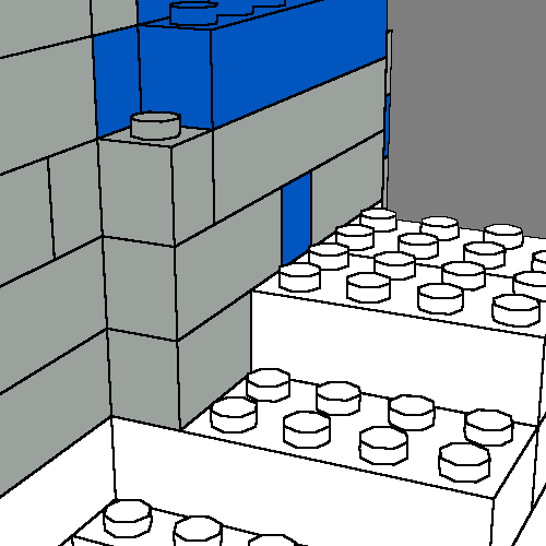
A simple renderer of the LEGO model, wouldn't show a clear distinction of the bricks (see Figure 1)It was fundamental to draw a border around different placements and around the studs, to aid understanding of the brick size. The way I solved this issue is through deferred rendering. The scene is first drawn into a gbuffer which hosts:
- the albedo map
- the depth map
- the outline guide
It is an integer number, that is different for every placement, and is different between the studs on top of the placement. When the gbuffer is ultimately drawn to screen, a convolution operation is performed: if at least one pixel within the kernel has a different outline guide, the central pixel is the outline and is set to be black.
App architecture
Don't get inspiration from this to authenticate users in your application.
When the conversion starts, a conversion thread is launched. This thread fires events to the main thread while the conversion is in progress. An example of an event is slice completion, this will trigger the generation of brick vertices, that are then baked in a GPU vertex buffer to progress the visualization of the LEGO construction.
